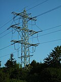
Transposition tower
This article needs to be updated. (March 2024) |
In electrical power transmission, a transposition tower is a transmission tower that changes the relative physical positions of the conductors of a transmission line in a Polyphase system. A transposition tower allows these sections to be connected together, while maintaining adequate clearance for the conductors. This is important since it distributes electrical impedances between phases of a circuit over time, reducing the problem of one conductor carrying more current than others.


Double-circuit lines are usually set up with conductors of the same phase placed opposite each other. This reduces the reactance due to mutual inductance; the reactance of both circuits together is less than half that of one circuit. For example, a section of a line may be (top-to-bottom) phases A-B-C on the left, also phases C'-B'-A' on the right. The next section may be B-C-A on the left, also A'-C'-B' on the right. Therefore, the rotation on each side of the tower will be opposite.[1]
Gallery
[edit]- Here, on the right the phases are rotated; on the left, two phases are swapped, thus the rotation sense changed.
- Transposition tower. On the right side, the phases are rotated upward, on the left side downward.
- Transposition in the span field of a 420 kV-line in Sweden
- Transposition on a single-phase line
- Transposition by using multiple towers
- Transposition by using elongated traverses
See also
[edit]External links
[edit]- ^ Technology, Electrical (2024-04-15). "Why are Conductor Positions Swapped in a Transposition Tower?". ELECTRICAL TECHNOLOGY. Retrieved 2024-08-23.


 French
 Deutsch


